|
 |
ТЕОРИЯ
Концентраторы "m-state" элементов
Исследование множества различных вариантов
генераторов "аксионного поля" показало то,
что непосредственно в генерации "аксионного поля" участвует очень маленькое количество вещества генератора, а
варьируется только качество его активации. Такое впечатление, что во всех
материалах присутствует одинаковое количество микро-примеси вещества, активно участвующего в генерации "аксионного поля".
Назовем эту примесь "m-state" элемент. Обычно количество этой микро-примеси пропорционально плотности вещества.
По-видимому, "m-state" элемент - это не обычный химический элемент или изотоп, это атомы с необычным (возбужденным) состоянием ядра. Эти атомы не обнаруживаются обычными физико-химическими методами. Для разработки методов обнаружения "m-state" элементов необходимо иметь их в большой концентрации. Но как их сконцентрировать?
На рисунке 1 показан концентратор "m-state" элементов.
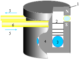 Где 1 - постоянный магнит,
2 - тонкие железные шайбы, 3 - вещество, аккумулирующее "m-state" элементы, 4 - центральный стержень магнита 1,
5 - направление движения жидкости в трубке 6 из немагнитного материала.
Где 1 - постоянный магнит,
2 - тонкие железные шайбы, 3 - вещество, аккумулирующее "m-state" элементы, 4 - центральный стержень магнита 1,
5 - направление движения жидкости в трубке 6 из немагнитного материала.
Во внутренней полости магнита 1 присутствует векторный потенциал, замкнутый вокруг его центрального стержня 4. Тонкие железные шайбы 2 с радиальными прорезями частично замыкают через себя рассеянное магнитное поле магнита 1, создавая градиент величины векторного потенциала по высоте полости магнита. Так что максимальная величина векторного потенциала будет в зоне 3.
Предполагается, что
магнитным полем "m-state" элементы будут
вытесняться из жидкости 5 во внутреннюю полость магнита, и дрейфовать в область
наибольшей величины векторного потенциала, т.е. в зону 3.Предполагается, что
магнитным полем "m-state" элементы будут
вытесняться из жидкости 5 во внутреннюю полость магнита, и дрейфовать в область
наибольшей величины векторного потенциала, т.е. в зону 3. В зоне 3 можно
поместить феррит или оптоволокно, которые будут применяться в генераторах
"аксионного поля". А можно поместить
сверхчистую воду для накопления в ней "m-state"
элементов.
Эту воду в дальнейшем можно использовать для биологических экспериментов или
использовать в физико-химических экспериментах по обнаружению и изучению
свойств "m-state" элементов.
Для "m-state" элементов стенки пробирок не являются препятствием. Если мы будем испарять воду, то, вероятно, в осадке "m-state" элементов мы не обнаружим. Но можно попробовать химически связать "m-state" элементы тяжелых ядер (золото, платина и т.д.) натрием или кислородом (O6).
Конструкцию магнита желательно сделать разборную на секции так, чтобы можно было изымать вещество, аккумулирующее "m-state" элементы (3), не пересекая магнитное поле магнита.
Для накопления "m-state" элементов желательно иметь постоянный, проточный поток вещества (по трубке 6). Это может быть вода, нефть, воздух или, например, движущийся алюминиевый провод.
Концентратор поглощает "m-state" элементы не только из потока вещества, проходящего через полюса магнита. "M-state" элементы интенсивно поглощаются из окружающей среды. Поэтому не известно, какие будут последствия для биологических объектов, длительное время находящихся вблизи концентратора.
Повышенную концентрацию "m-state" элементов можно наблюдать в горах, в точках
повышенной напряженности "гео-поля", вдоль
линий ЛЭП и их подстанций, около топок ТЭЦ, и, особенно, около ядерных
реакторов и хранилищ радиоактивных отходов. В таких зонах для сбора рассеянных
"m-state" элементов можно использовать
конструкцию, аналогичную показанной на Рис.1, но без горизонтальной прорези под
трубку 6 (магнит с полным замыканием магнитного поля), но с четырьмя узкими (в
толщину стенки) радиальными (вертикальными) прорезями.
Для сбора "m-state"
элементов такую модернизированную конструкцию можно просто опускать в реку или
в поток морских течений.Предполагается,
что для образования "m-state" элементов
необходимо затратить более 10 keV энергии на одно
ядро атома.
Хорошими кандидатами на производство "m-state" элементов являются электроннолучевые (TV) трубки современных цветных телевизоров и компьютерных мониторов. Струи потоков "m-state" элементов из TV трубки в основном наблюдаются вдоль плоскости теневой маски (вдоль плоскости экрана). Количество и направление струй определяется геометрией TV трубки и корпуса (монитора). Для сбора "m-state" элементов от TV трубок лучше подходит конструкция, показанная на рис.2 (в разрезе).
Где 1 и 3 - ферритовые трубки с низкой электрической проводимостью, 2 - ферритовое колечко (в котором производится концентрация "m-state" элементов), 4 - графитовый диск, 5 и 6 - внешние и внутренние медные электроды.
При сборке конструкции вначале внешняя и внутренняя поверхность ферритовых трубок 1 и 3 покрывается графитом, а затем к ним плотно прижимаются электроды 5 и 6 (или эти электроды получают электролитическим осаждение меди на графит).
На электрические тороидальные катушки через выводы 11,12 и 13,14 подается электрический ток так, что в
ферритовых трубках 1 и 3 магнитное поле имеет противоположное направление. При
этом и векторный потенциал внутри трубок имеет противоположную направленность.
А в зоне ферритового кольца 2 векторный потенциал трубок 1 и 3 суммируются в
радиальной компоненте.
Электрический ток в обмотках должен обеспечивать магнитное поле, близкое к величине магнитного насыщения ферритовых трубок 1 и 3. Конструкция будет значительно проще, если вместо ферритовых трубок использовать постоянные магниты с низкой электрической проводимостью.
На выводы 7,8 и 9,8 электродов 5 и 6 соответствующих трубок 1 и 3 также подается электрическое напряжение противоположного знака так, что в обеих ферритовых трубках формируются перпендикулярные магнитные и электрические поля с вектором Пойтинга, направленным вверх.
Данная конструкция работает сразу по двум факторам:
1. Концентрация "m-state" элементов в зоне наибольшей величины векторного потенциал (зона кольца 2) путем концентрации "аксионного поля" "m-state" элементов в этой зоне;
2. Концентрация "m-state" элементов путем концентрации их "аксионного поля" типа 3 с использованием вектора Пойтинга.
3.
(Аналогия - железные опилки втягиваются в область наибольшей напряженности магнитного поля; предполагается, что "m-state" элементы втягиваются в область наибольшей плотности "аксионного поля".)
Использование материалов, насыщенных "m-state" элементами, в генераторах "аксионного поля" заметно повышает эффективность генерации "аксионного поля". И предела насыщения материалов "m-state" элементами пока не обнаружено.
Есть предположение, что существует некоторая критическая концентрация "m-state" элементов, выше которой предмет становится "магическим", и должны проявить себя необычные эффекты (например, технотронный полтергейст).
Водяные ловушки m-state элементов.
Как это делают буржуи.
Theory:
We believe that the m-state (ORMUS) materials dissolved in water are superconductors which respond to magnetic fields. We have observed that most water, when swirled in the presence of a magnetic field can be separated into two components; a magnetically responsive component and a non-responsive component. Magnetic traps of various designs have been devised to take advantage of this property in order to concentrate a form of the ORMUS elements. This concentrate tends to be "oilier" than ordinary water, it also tends to be lighter than ordinary water when it is moving in relation to magnetic fields but it tends to be heavier than water when it is stationary in relation to magnetic fields. According to a theory developed by the inventor of the magnetic trap, different m-state elements may have different magnetic repulsion characteristics. This might allow us to design traps which will separate the different m-state elements.
Теория:
Мы предполагаем, что M-стейт элементы, растворенне в воде являются суперпроводниками, которые отвечают на магнитные поля. Мы наблюдали, что вода, протекающая в присутствии магнитного поля может быть разделена на 2 компонента: магниточувствительный компонент и магнитонечувствительный компонент. Магнитные ловушки различых конструкций были разработан как раз для того, что бы извлечь пользу от этих свойств воды – для того, чтобы сконцентрировать M-state элемент. Этот концентрат стремится быть более маслянистым, чем обычная вода, он обычно легче по весу, чем обычная вода, когда она движется под воздействием магнитных полей. В соответствии с теорией, разработанной автороммагнитных ловушек, различные m-state элементы могут иметь разные магнитные характеристики. Это может позволить нам собирать ловушки, позволяющие собирать различные m-state элементы.
Assembly Instructions
Интструкции по сборке
Instructions for constructing a storage magnetic trap to concentrate m-state materials in water.
Инструкции для постройки магнитной ловушки m-state элементов для того, чтобы сконцентрировать их в воде.
The device described in this document is proprietary. You were given this information so that you can attempt to verify the theory which this device seems to demonstrate. Please keep this information confidential; do not discuss it with anyone.
Устройство, описанное в этом документе – собственность. Вам предоставляется эта информация для того, чтобы вы предприняли попытку, чтобы подтвердить теорию, которую демонстрирует устройство. Пожалуйста, сохраняйте эту информацию конфиденциальной, не подвергайте это обсуждению ни с кем.
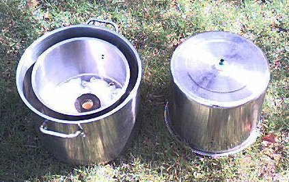
We recommend using cheap stainless steel stock posts since they are more likely to be attracted to a magnet. The stainless steel pots must be able to hold a magnet stuck to their surface.
Construction
Stock pot preparation:
Remove the handles on the two smaller stock pots. This can be done by drilling or grinding the rivets that hold the handles on. These handles are usually held on using aluminum rivets.
Drill or cut a ¾ inch hole in the exact center of the bottom of the mid sized (12 inch) stock pot.
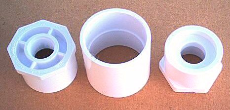
Inlet assembly:
The inlet assembly is constructed from the PVC pipe parts and the O rings. Insert the close nipple into the hole in the center of the bottom of the mid sized (12 inch) stock pot and put both O rings on the nipple from each side. One of the PVC threaded couplers threads onto the part of the nipple projecting from the outside of the stock pot and the other threads onto the inside. The portion of this assembly which passes through the lid should be tightened with wrenches. You should use Teflon tape on these joints if you wish to take them apart later.
The plastic or brass ½ inch thread to 3/8 inch hose barb screws into the threaded coupler on the outside of the 12 inch stock pot. When you are ready to use the magnetic trap, you can attach a piece of vinyl tubing between this hose barb and your water source.

Vinyl tubing, hose barb and hose coupler
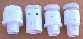
Nozzle:
You build the nozzle portion of the inlet assembly by pushing the ½ inch male plug into the unthreaded end of the ½ inch PVC to male pipe thread adapter. Then you pound this plug into the adapter with the threaded end of the adapter against a block of wood so it will not be damaged.

Nozzel parts
Drill four to six 1/8 or 1/16 inch holes through the side of the adapter into the center of the plug so that the holes enter the center of the plug at a tangent to the circumference of the space inside the plug. In other words, we want the water to come out the side of the inlet assembly in such a way as to create a pinwheel effect which will move the water in the trap in a circular motion parallel to the bottom of the inner stock pot about midway between the magnets.

Finished nozzel assembly
The PVC pipe to male thread adapter screws into the threaded coupler projecting from the inside of the 12 inch stock pot. This male pipe thread adapter can be threaded into the female coupler hand tight as this will allow you to experiment with different nozzles to swirl the water inside the trap.
Nozzle assembly and coupler
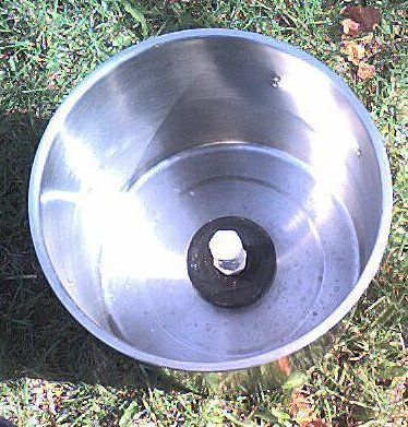
Magnet assemblies:
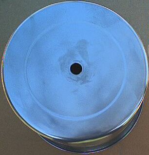
The two speaker magnet assemblies from discarded speakers must be disassembled. These magnet assemblies consist of two steel plates glued to the top and bottom of the donut shaped magnet. While you can break these steel plates loose from the magnet with the hammer and chisel, you run a great risk of breaking the magnet in the process. If you first heat the metal plates on a burner, the glue will soften and it will be quite easy to separate the metal plate from the magnet. Apply heat to the steel plate, not directly to the magnet. Be careful not to apply too much heat for too long; heat can weaken a magnet. The lower magnet should be smaller than the upper magnet.

Lower and upper magnets
Upper magnet
assembly:
After you have separated the speaker magnets
from the metal plates they must be coated with silicon sealer and set to dry.
When the magnets are dry you can attach the larger of them to the inside of the
12 inch stock pot so that the nozzle assembly protrudes through the center of
the magnet. Since the stock pots are made of cheap stainless steel, the magnet
will probably hold itself to the bottom inside of the 12 quart stock pot quite
nicely. This magnetic attachment method will also allow you to experiment with
the orientation of the magnet. We believe that the two magnets should be
mounted so that they attract each other but this is not totally confirmed.
12 quart stock pot with upper magnet and nozzle assembly
Lower magnet
assembly:
The bottom magnet will be suspended on a pedestal which is centered in the
bottom of the 8 inch pot so that the top of this magnet is about four to five
inches away from the bottom of the upper magnet. This magnet must be isolated
from contact with the walls and bottom of the inner-most 8 quart stock pot. It
will be supported on a PVC pedestal.
Pedestal parts
Pedestal assembly:
Trim ½ inch off each end of the 2 inch
PVC coupler. Trim both 2 inch to 1 inch PVC reducers so that they are 1 inch thick. Glue each reducer into an end of the 2 inch PVC
coupler.

Completed pedestal assembly
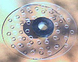
Acrylic disk:
Take the 12 inch square of clear acrylic and determine the center of the large
surface.(This is easily done by determining where
lines drawn from opposing corners intersect.) Drill an 1/8 inch pilot hole through the center point which you have just determined.
Using this hole as a pivot, scribe a circle on the acrylic square which is
slightly smaller in diameter than the inside diameter of the 8 quart stock pot.
Using the coping saw or a sabre saw, cut the acrylic square into a circle using the scribed line as a guide. Using
the pilot hole in the acrylic circle as a guide, cut a hole in the center using
the 1½ inch hole saw. Drill a bunch of half inch holes at random points
spaced about an inch apart across the rest of the acrylic circle as illustrated
in the image below.
Acrylic disk hole plan
Take the 1½ inch piece of 1 inch PVC pipe and cut a single slot half way down one side using the hack saw. Cut two slots half way down from the other end oriented so that they don't intersect the single slot from the other end. Insert this piece of pipe into the center hole of the acrylic circle. Put the center hole of the smaller magnet over the two slot end of the pipe section. If it fits snugly, the magnet should be glued (using silicon sealer) to the short piece of 1 inch pipe.
Magnet, acrylic disk and pipe section
Slip the single slot end into one end of the pedestal assembly. This fit should not be so tight as these two pieces will be separated every time the trap is used. This completes the construction of the lower magnet assembly.
Check the fit of this completed assembly. It should slip easily into the 8 quart stock pot. Glue the bottom of this assembly to the inside bottom of the 8 quart stock pot using the silicon sealer. The acrylic circle should keep the pedestal centered while the silicon hardens. Allow the silicon to set for 8 hours.

Lower magnet assembly, acrylic disk and pedestal inside 12 inch pot
X-shaped spacer:
You will need an x-shaped spacer to keep the inner 8 quart stock pot from resting on the bottom of the outer 16 quart stock pot. You can build this by cutting two half inch thick pieces of acrylic or other plastic 1 inch wide by 16 inches long with a half inch deep notch out of both top corners of each end of them and a centered notch so that they can be assembled in a cross shape. These pieces will look somewhat like this:
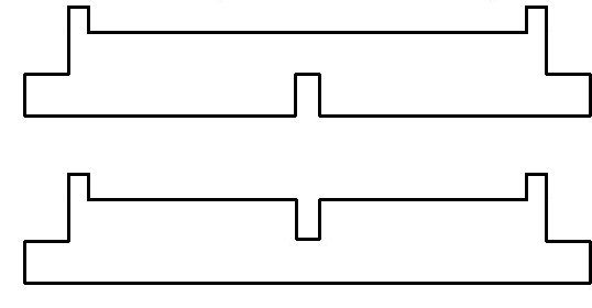
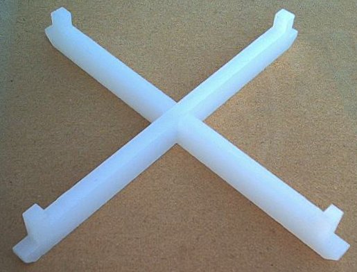
Assembled x-shaped spacer
Final assembly
After the silicon sealer has fully cured, lift the lower magnet and acrylic disk up from the pedestal assembly. Loosly fill the inner 8 quart stock pot around the pedestal assembly with some polyfill or similar material up to about the top of the pedestal assembly and replace the magnet and acrylic disk.

Polyfill beneath magnet and acrylic circle
The 16 quart stock pot rests on it's bottom. Place the x-shaped spacer in the bottom of the 16 quart stock pot. Put some polyfill between the arms of the x-shaped spacer.
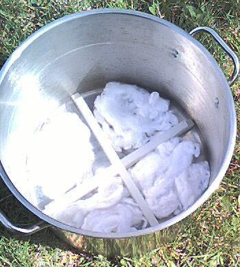
Polyfill between arms of x-shaped spacer
Center the 8 quart stock pot upright inside the 16 quart stock pot.
Ready for final assembly
Invert the 12 quart stock pot and slip it down between the 8 and 16 quart stock pots. The x shaped spacer will center the inverted 12 quart pot so that it's open end is one half inch above the bottom of the 16 quart pot.
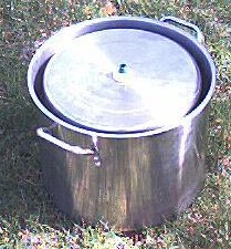
Assembled trap
Here is a diagram of the cross section of the completed trap showing the three interlocked pots, the inlet/nozzle assembly and the two magnets (the x shaped piece in the bottom of the 16 inch pot is not shown for clarity):

Operation:
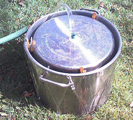
Run water into the inlet pipe at the top of the Storage Magnetic Trap for several hours.The 12 quart stock pot will trap a bubble of air as the other stock pots are filled with water. To keep the inverted 12 quart stock pot from floating up as it is filling, wedge three clothespins between it and the outer stock pot. You will need to release the trapped air bubble. Drill a 1/16 inch hole in the bottom of the 12 quart pot. When the air has quit bubbling out you can plug this hole with a toothpick.
Shows clothspins and air bubbling out of inverted 12
quart pot
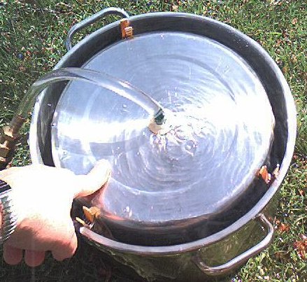
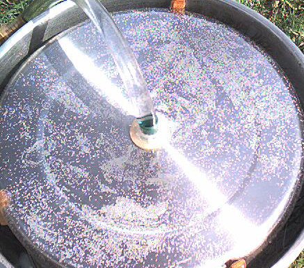
Here are a couple of views of the Storage Magnetic Trap in operation:
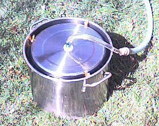
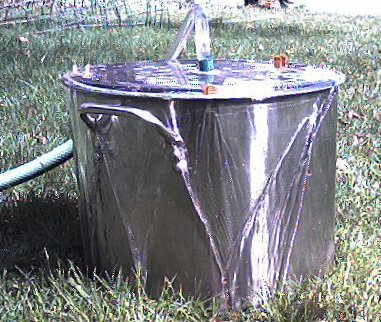
In the following two pictures notice the bubbles clinging to the bottom of the inverted 12 quart stock pot. These bubbles will remain stable for a long time after the water is shut off. The second picture was taken half an hour after the water was shut off.
Experiments:
Test for m-state using the ether method and/or by tasting the water and feeling its viscosity.
Change the length of time the water flows through the device.
Change the swirl rate by constructing different nozzle sizes and configurations.
Assorted nozzel configurations
Change the swirl direction.
Change magnetic polarity. There are four possible magnetic field combinations between the adjoining faces of the two magnets: North-south, north-north, south-south, and south-north.
Experiment with inflow and outflow rate.
Experiment with circuitous outflow paths.
Experiment with galvanized pipe as the inflow tube.
Try a stainless steel or plastic "twisted ribbon" type device to swirl the input water as it passes the top magnet on its way in.


Как это можно сделать у нас
Собираем конструкцию тройника-ловушки.
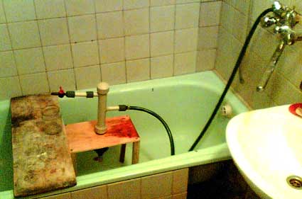
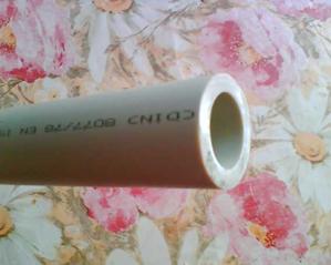
Возьмите пластиковую трубу диаметром 40мм
Отрежьте ее нужной Вам длины. Приблизительно длина составляет 40 - 60 см.
Центральная труба выполняет роль отстойника, в которой
m-state элементы поднимаются на поверхность.

К центральной трубе будут подсоединены 3 рукава: два по бокам, и один дренажный, в торце внизу
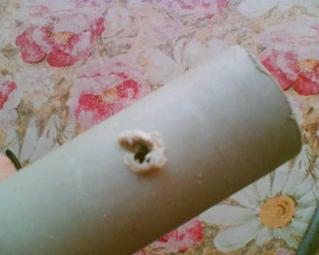
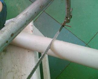
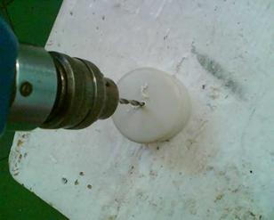
Для присоединения просверливаем отверстие, которое потом нужно будет расширить до необходимого диаметра (20мм) при помощи 100 ватного паяльника.

Постепенно включая и выключая паяльник, добиваясь плавной регулировки нужной для пайки температуры пропаиваем отверстие необходимого диаметра.

Подготавливаем рукава, предварительно вырезав 2 необходимой длины кусочка из ½ дюймовой трубы (20мм)
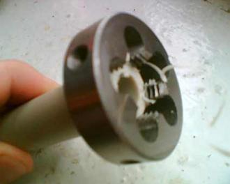
Для того, чтобы нарезать резьбу понадосится лерка на полдюйма.

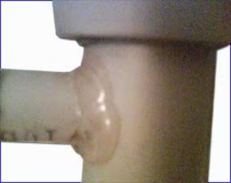
С 2 сторон центральная труба будет закрыта заглушками
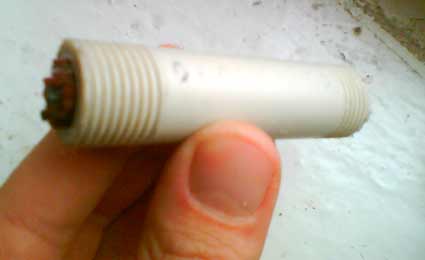
В одну из этих заглушек будет впаен выходной штуцер диаметром ½ дюйма
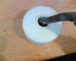
Проделываем такую же процедуру паяльником, подготавливая отверстие для дренажной трубки

Разогреваем саму трубку перед присоединением на газовой плитке, равномерно вращая образец
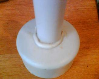
вставляем расплавленный конец трубки в заглушку, предварительно поддерживая температуру отверстия паяльником

Для более прочного шва обрабатываем стык термоклеем
Такую же операцию проделываем с центральным и выходными отверстиями
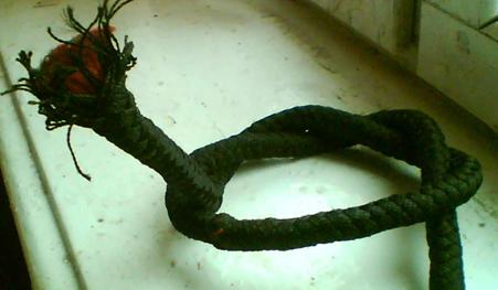
Важная часть – изготовление фильтра. Для этого нам понадобится толстая нейлоновая сногожильная веревка

Расплетаем ее наружную часть и вырезаем кусок нужной длины (в раза больше чем выкодной коллектор)

Перевязываем пополам
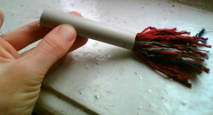
Протягиваем нити заполняя выходной штуцер
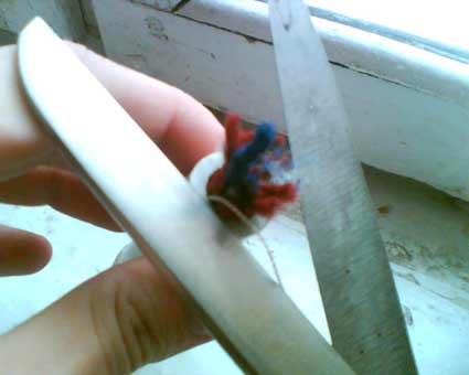
Аккуратно обрезаем конец фильтра
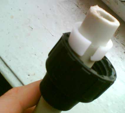
Вот так выгдяжит фильр в сборе с нарезанной резьбой, готовый к присоединению к основной части

Фильтр, как и другие части присоединяется с гибким шлангам при помощи пластиковых муфт
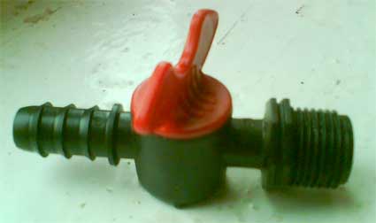
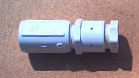
На выходной патрубок нам понадобится пластиковый краник
Подготавливаем выходной патрубок, на котором будут расположены магниты.
Для этого нам понадобится переходная муфта
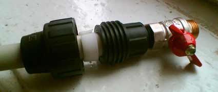
, которую насаживаем на выходную трубу и присоединяем дренажный краник
Нам понадобится ряд магнитов, которые насаживаем на выходной патрубок

Проверяем полярность установки, для этого необходим компас
Входной шланг подсоединяем к крану
В итоге конструкция собрана и готова к работе
После сборки конструкции необходимо настроить ловушку. Делается это последовательной регулировкой дренажного крана и крана сбора готовой продукции. Включаем кран холодной воды и настраиваем краны до уровня, когда на выходе происходит капание почти переходящее в течение.
Вода с собранными m-state элементам напоминает шампанское и имеет своеобразный привкус. При принятии вовнутрь можете почувствовать приятный прилив энергии и легкость в теле.
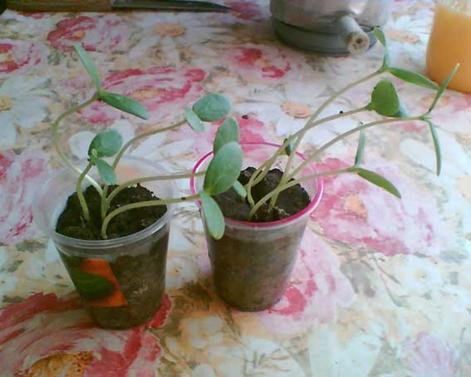
Проба воды на растениях
Влияние воды требует тщательного исследования . Для начала я попробовал посадить несколько растений и посмотреть на то как будут развиваться растения при поливе их разной водой. Результаты были наглядными.

Первые попавшиеся растения купил на распродаже
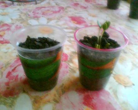
Лук был посажен 16-го числа. Эта фотография сделана 23 числа. Красным обозначен стаканчик, который поливался водой с содержанием m-state элементов

Это тот же самый лук 26 числа
Это тот же самый лук 30числа
А это семена огурцов 23 числа. Посажены вместе с луком одновременно. 16-го числа

А это результат ближе к 30 числу.